Form and Position of MIM Glue Feeding Point
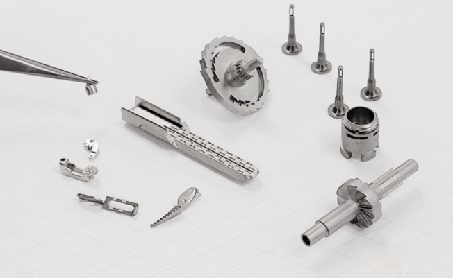
Glue feeding point: form and position
Just like plastic injection molding, MIM parts must also consider the type and location of the injection point. In any case, the opening of the glue injection point of the MIM must be larger, because a large proportion of the solid metal powder in the MIM is mixed with low molecular weight materials with high fluidity, which is much higher than that of pure plastic (it is easy to "run out" of the burr).
In most design schemes, the glue injection point is usually located on the parting line, so the consideration of the position of the glue injection point should try not to destroy or affect the function of the part, including the feasibility of manufacturing, function, dimensional accuracy and appearance. The glue injection point will leave some indentation, and it should not fall on the important size area or the important appearance position in design, which must be noted. Generally, it is suggested that the glue injection point should fall on the thicker area, so that the high-viscosity ejected material can flow from the thickest place, and at the same time, it should be considered that the mold cavity can be filled evenly. As shown in Figures 1 to 5, three different glue injection point designs and descriptions are often used.
•The characteristics of the side edge glue entry point are as follows:
• The sprue on the formed green billet must be cut manually by itself, so the possibility of high automation is very low, which is not suitable for mass production. In any case, the cost of manual removal will be included in the cost.
• Suitable for MIM parts with small output. (The mold structure is simple and the processing cost is low).
• The concave glue feeding point is recommended, but the appearance and function should be considered (see Figure 2).
• Normally set at the position of parting line.
The characteristics of submersible glue feeding point are as follows:
• During the demoulding process, the material head falling into the glue point can be directly removed.
• MIM parts suitable for any production.
• Leaving small concave marks like leaves on the green surface. However, it should be noted that too small glue inlet may cause injection difficulties.
• The submersible glue feeding point can hide the smallest trace on a concave surface of the part.
• The processing cost of the submerged processing mold is higher than that of the edge rubber inlet.
The submersible glue feeding point (periscope type) designed on an extended column has the following characteristics:
• During the demoulding process, the material head falling into the glue point can be directly removed.
• The green billet such as the extended cylinder can be removed after being taken out of the mold, but
It cannot be removed automatically.
• The submerged glue injection point can be hidden on a concave surface of the part to form a hole mark, where the extended cylinder can be broken during mold opening.
• MIM parts suitable for any production.
• The position of extending the cylinder, exiting the dent or cavity mark cannot be placed on the appearance surface.
Unless the customer has not specified the treatment method for the glue inlet, you can keep the glue inlet trace. If it is necessary to polish the glue point, a certain polishing thickness is required after sintering to completely remove the trace. Adopt prominent glue feeding points and minimize polishing amount. Just like picture 5 as below.
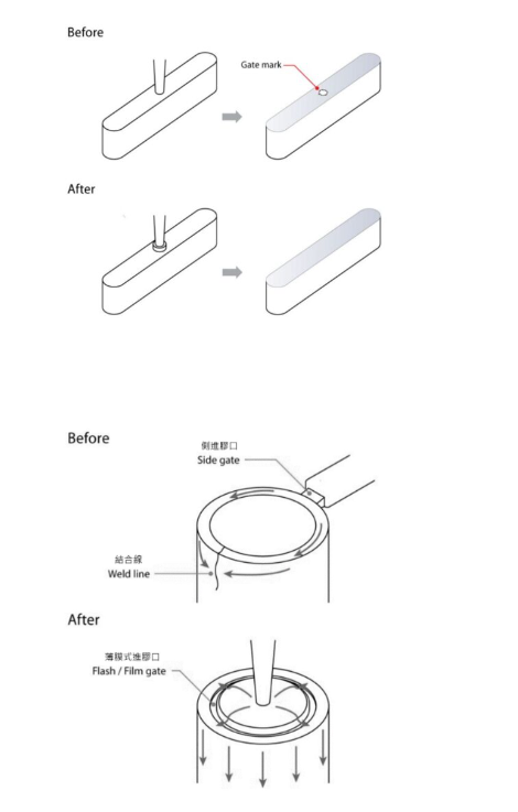
If we use the traditional rubber mouth side feeding, serious dents and bonding lines may be seen at the junction point of the large pipe mouth. Shrinkage marks and the appearance of the binding line cause deformation and poor mechanical properties, and reduce roundness. The watch shell structure has similar characteristics. Use film or flash type glue inlet to eliminate welding line and improve roundness tolerance.
As shown in Figure 6, the advantages of changing the side glue feeding mode to the thin mode for comprehensive glue feeding.
Of course, other injection point designs used in plastic injection molding can also be used in MIM part molding. For example, the direct injection point for three-plate mold, the direct injection point for hot runner, and so on, because the technology of MIM is based on the plastic injection technology. The mold cost is an important consideration when you select a non-general glue injection point.
Barb: external and internal and hollow structure
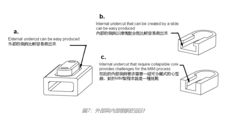
The external barb is relatively easy to achieve. The main reason is that there is enough space for the slider or insert to place and move. As shown in Figure 7 a., an external barb design reduces the burr of parts requiring mating parts. This design can be easily designed on MIM products, without the cost of removing the burr in the later process stamping. In essence, it is a good way to reduce the post-processing of parts by adding a little complex design, and it is the most important to avoid the second processing. For assembly parts, MIM design also needs to be imported from the time of design to solve the problem of later manufacturing process.
Of course, the internal barb can also be achieved by using the MIM process, and the combined slider or cylinder block can achieve this purpose. The "T slot" shown in Figure 7 b. is a typical barb structure, which can be easily achieved by using the side slider (the possible manufacturing costs and maintenance costs of more than one slider should also be considered). As shown in Figure 7 c., the closed barb needs to be completed by using the foldable insert and slider, and at the same time, it must have sufficient space capacity and strong enough mechanism. Generally, the size of MIM parts is very small, so it is impractical or even impossible to design detachable inserts and sliders.
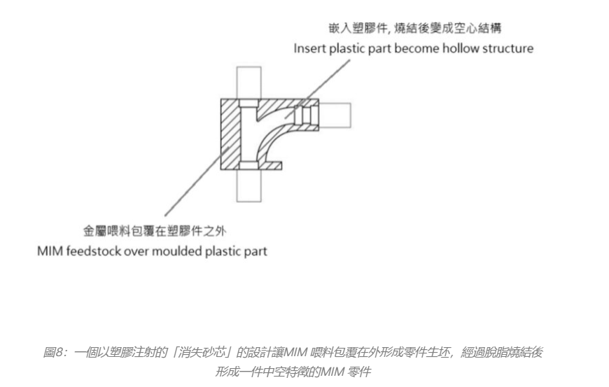
With the application of 3D-MIM technology, complex hollow designs or micro-dimension configurations can be generated on a large scale, and hollow MIM parts can be obtained by feeding the injection of the moldable inserts, as shown in Figure 8.
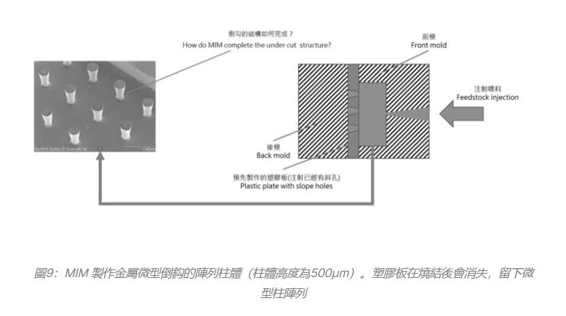
The technology of eliminating auxiliary parts above can even minimize the design limit. How does MIM complete the matrix structure of barb column? The answer is a thin plastic adhesive layer with inclined holes. MIM feed can be injected into these inclined holes to form an inverted structure. See Figure 9.
Threads: external and internal
The internal hole thread of MIM parts can be directly formed by the thread rotor during the injection process. Parts with such features and functions are relatively expensive in production. Unless the quantity of products is really large and necessary, it is not recommended to complete the screw hole on the injection machine, and it is better to directly tap the thread twice. Even if the quantity is large, it can be executed with semi-automatic or full-automatic equipment. The two main reasons are that the upper tapping time of the ejector is very long and the MIM green is very fragile.
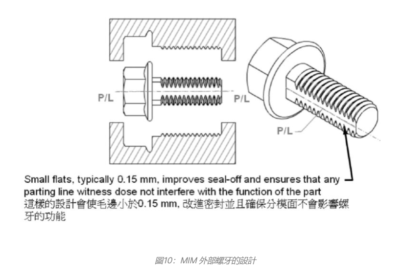
The external thread can be directly formed by the mold, which is not a problem. This method is economical and efficient, and does not require secondary processing and costs more. Generally, adding a small plane (about 1.5mm wide) can avoid the dislocation burr of the joint. As shown in Figure 10, in addition to improving the sealing of the mold, the production efficiency can also be improved. Although it may increase the cost of the mold, increasing the yield rate can save a lot of unnecessary troubles. Such a design can be considered.
Ribs and bridges
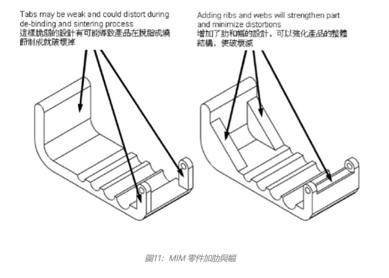
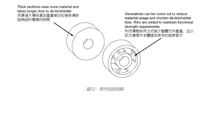
Ribs and bridges are a structural design that can effectively improve the strength of products and reduce the size variation caused by shrinkage, especially in the process of degreasing and shrinkage. Just like plastic injection molding, ribs and bridges also provide better molding and dimensional control. Figure 11 shows that the arrangement of ribs and bridges can improve the mechanical strength of MIM products, including the fragile MIM green before sintering. Other applications are shown in Figure 12. Ribs and bridges are designed to reduce the weight of parts and provide the same functions as the original ones, and even strengthen the parts.
Knurling, letters and signs
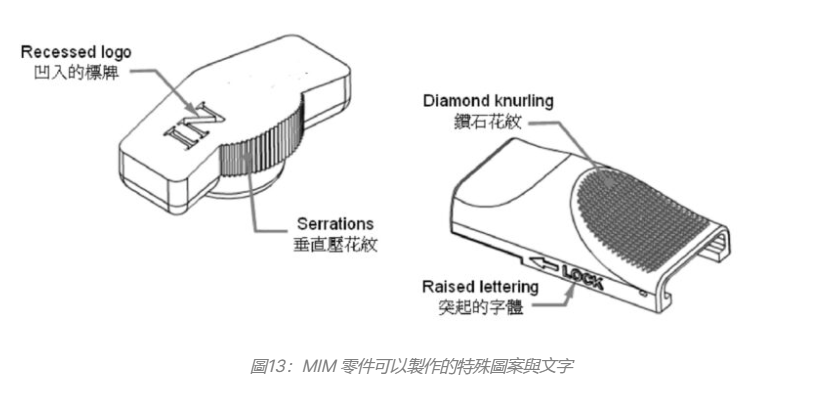
MIM can be used as knurling, letter, sign, date code or other designs that can be directly put into the sign without extra costs (a little is necessary because it is necessary to carve characters on the electrode for use in electrical discharge machining). These features can be required to be concave or protruding from the surface of the object. As shown in Figure 13, some features are designed to be used as knurls, characters, signs, date codes or other direct patterns on the surface of MIM parts, so engineers have a variety of imaginations to implement the design.
Shrinkage and knife mark/binding line
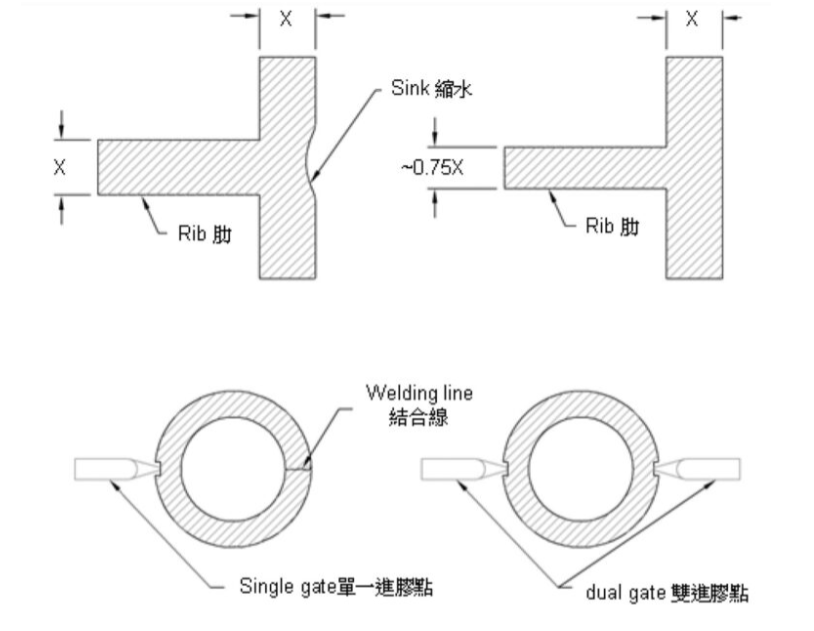
Like plastic injection parts, MIM parts may also have shrinkage and flow marks, which is due to improper design of parts and molds. Shrinkage (a biological depression on the surface of the part) often occurs in places with more thickness. Figure 14 shows that if shrinkage occurs in a design where the thickness of the rib is the same as the thickness of the wall (referring to the wall that forms the appearance surface), the thickness of the rib should be adjusted to be slightly smaller than the thickness of the wall. Adjusting the rib thickness is helpful to avoid shrinkage on the appearance surface or necessary structural surface. Usually, 75% of the wall thickness is used as the rib thickness. If the design of a hollow column is placed inside the shell, the root of the hollow column must be cleaned to prevent the external surface of the shell from contracting.
Knife mark is also known as the binding line (Chinese system). Due to the structural barrier of the mold cavity, two strands of molten material converge through a long path, and some materials have solidified before reaching the confluence point, resulting in the binding line.
Figure 14 (lower left figure) shows that a MIM part creates a typical binding line with a single glue injection point. Because the central pin block causes two lines of material to form and flow after a long distance, the obvious binding line will appear on the opposite side of the glue injection point. As shown in Figure 14 (lower right figure), adding a glue feeding point can shorten the stroke length of the rubber, and it is not easy to produce cold material and binding line. In theory, the binding line that does not affect the function should be ignored, but it should be noted that if the MIM part is a functional part that bears repeated stress or thermal cycle under adverse conditions, the binding line cannot be allowed. Generally speaking, the acceptable binding line should be within the range of 0.01~0.1mm in width, which looks like a line.
