en
 de
 jp
 kor
 fra
 spa
 ru
 pt
 it


5-Axis CNC Machining Tolerances: Standard Guide for Precision Components
The following text describes 5-axis CNC machining tolerances and shows why those measurements are necessary to create accurate, reliable plus precise components. To produce complex geometries and angled features on multiple surfaces with few setups, the machine moves along three linear axes but also rotates on two additional axes. The dimensional accuracy and consistent quality are necessary because the components must fit together as well as function correctly during assembly. It is important to select proper tolerances so that the parts perform their intended tasks. As the process unfolds, the achievable tolerances change based on the material, the capability of the machine, the tools, the devices that hold the work and the methods of inspection - this article is a practical guide that details standard tolerance ranges or industry standards. There are descriptions of the factors that influence the measurements and instructions on how to maintain consistent precision during the manufacturing process.
What Are 5-Axis CNC Machining Tolerances?
Define 5 Axis CNC Machining Tolerances: This is the tolerance limit that is allowed between the dimensions as specified in the design and the manufactured dimensions of the parts. Provide an explanation as to how tolerances influence a part's design, functional and assembly requirements. Explain tolerances like dimensional, angular and geometric tolerances like flatness, perpendicularity, parallelism and position. Explain the difference between machine placement accuracy and machine product tolerance - the product is affected by the whole manufacturing process.
Standard Tolerances for 5-Axis CNC Machining
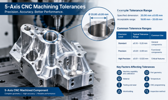
Discuss the tolerances values that are commonly applicable in the standard, precision and high precision CNC manufacturing. Explain the differences between the general machining requirements and what is required for a component to provide accurate fits, alignment and complex geometric relationships. Use an example table to show common reference ranges to help the reader become aware of the normal range based on a generic manufacturing list and to indicate that this is based on expected manufacturing capability, not a guaranteed list.
Precision Level | Typical Tolerance Range | Common Applications |
Standard | ±0.10–0.20 mm | General mechanical parts |
Precision | ±0.03–0.08 mm | Functional components |
High Precision | ±0.01–0.025 mm | Critical precision features |
Describe that there are material - feature size - shape - machine condition - and manufacturing requirements dependent tolerances for actual tolerances. Remind manufacturers that they need to validate tolerances that are practical for manufacturing with a design-for-manufacturing review.
ISO Standards Used for CNC Machining Tolerances
Describe the role that international standards play for engineers, designers and manufacturers, in communicating dimensional and geometric information easily. Let ISO 2768 be recognized as a general tolerance standard for dimensions that are not specified by individual tolerance for engineering drawings.
ISO 2768 General Tolerances
Explain both part A and B of ISO 2768 (ISO 2768-1 – linear and angular dimensions and ISO 2768-2 – general geometrical tolerances). Describe fine, medium, coarse and very coarse tolerances and how the engineer would use a specific class for a component. Explain that the tolerances for individual parts are more specific than general drawing tolerances. Explain that the tolerance class could be used to simplify the drawing but still allow for the same tolerances in finished product.
GD&T and Feature-Specific Tolerances
Explain the meaning of Geometric Dimensioning and Tolerancing (GD&T), which is the control of by the byproduct of a component's form, orientation, location and relationship to features. Describe the significance of flatness of a surface, perpendicularity of a feature and position of a hole and mounting pattern, and profile of a complex curve surface. Explain briefly what datums are and describe them as a reference point, axis or surface for the definition of or inspection of geometric relationships. Describe when GD&T is particularly beneficial in the case of "5-axis" parts that have features that must be aligned and functional to each other.
What Affects 5-Axis CNC Machining Tolerances?
Discuss about the various manufacturing factors affecting the dimensional accuracy and repeatability. Outline the effect of machine calibration, rotary axis alignment and machine condition on the precision of complex machining processes. Explain the phenomenon of different material reactivities to cutting forces and changes of temperature when cut with various materials such as aluminium, stainless steel, titanium and engineering plastics. Account for part geometry, such as thin walls, deep cavities, small holes and angled parts, which can lead to increased tool deflection and/or workpiece deformation. Explain what can happen when tools get worn, what cutting parameters they are, and workholding rigidity, vibrators, thermal expansion, and programming. Explain that depending on them to relate them all to quality control will help produce high quality products.
Why 5-Axis Machining Can Improve Feature-to-Feature Accuracy
Discuss how to use 5-axis machining to affect dimensional relationships in fewer setups to machine multiple surfaces and features at angles. Explain why decreasing repositioning efforts and re-fixturing can help to reduce alignment errors and resultant positional variation between features. Explain the feasibility of making use of it to make complicated housing, aerospace parts, automotive part and precision industrial component which need multi-face machining. Explain that 5-axis technology cannot necessarily provide closer individual tolerances than can 3 axis technology. It can be useful in terms of setup reduction, depending on the machine and process, to provide more consistent features to features.
Tolerance Requirements for Different Precision Components
Discuss the different tolerances based on the function, geometry and operating conditions of a component. Explain holes and bores in which precise dimensions for bearings, pins and fasteners, as well as flatness and alignment for mating surfaces must be maintained. Include angled components, curved surfaces, and frail parts capable of thin walls that demand precise positioning, toolpath and machining forces and heat control. Where positional accuracy is important in assembly and functioning, add mounting. Emphasize that a designer should not specify an overly tight tolerance for any feature; instead he must determine the critical-to-function dimensions and specify only those that set a limit that is acceptable for function during manufacturing. The strategy will keep components reliable and maintain the production time and cost control.
How Are 5-Axis CNC Machined Parts Inspected?
Explain how inspections are carried out for the verification that the finished components are compliant with engineering drawings. Describe the use of a micrometer, a digital caliper and a height gauge to measure general dimension, precision dimension, and height and positional reference. Explain Coordinate Measuring Machines (CMMs) and the use to check complex geometry, position of holes, datum relationship and geometric tolerances Use surface measurement instruments for checking for surface roughness as required. Describe the purpose of first article inspection, in process measurement and final inspection reports in meeting the quality and consistency of manufacture. Make sure that they clearly realize the appropriate inspection equipment should be selected for the needed tolerance and the part geometry.
How to Specify Tolerances on a 5-Axis CNC Drawing
Thoughtfully explain the process and materials used in engineers and product designers to create technical drawings for precision manufacturing. Describe why it is important to accurately specify the functional requirements, critical dimensions and use limited tolerances as necessary for the component. Suggest the selection of an appropriate general tolerance standard, the use of GD&T for critical geometric relationships and the use of datum defintion. Discuss the importance of considering material properties, access to the machines, work-holding and inspection needs before the finalising of tolerances by the designer. Implement guidelines and recommendations for review of drawings by the manufacturer and design team to insure that the required tolerances can be realized within a reasonable commercial realization.
Best Practices for Achieving Consistent 5-Axis CNC Tolerances
Outline the measures that manufacturing companies can adopt in order to gain repeatable dimensional accuracy. Add inspection of machine calibration, choice of appropriate tools, cutting parameters optimisation, rigid workhold fixture and the optimised parameters of toolpath planning. Discuss why unnecessary set-ups should be avoided, how to control tool wear, that heat and stress should be kept to a low level and stable conditions should be maintained when working on sensitive materials and parts. Discuss also the importance of Datum set up, suitable inspection equipment, regular quality checking during the production. Highlight that carrying out these practices in addition to DFM reviews will result in better consistency of parts and minimise waste in production.
5-Axis CNC Machining Tolerances vs. 3-Axis Machining
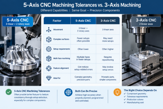
Factor | 3-Axis CNC | 5-Axis CNC |
Movement | 3 linear axes | 3 linear + 2 rotary axes |
Complex surfaces | May need more setups | Fewer setups often possible |
Setup requirements | Often higher | Often lower |
Multi-face machining | Requires repositioning | Multiple faces in fewer setups |
Feature alignment | May involve setup errors | Can reduce setup-related errors |
Conclusion
Explain the impact of 5-axis CNC Machining Tolerances on the precision components' accuracy, usability, and dependability. Educate pupils that obtaining good tolerances is not just about having well advanced machinery, but also about material, tooling, work holding, programming, temperature control, and inspection techniques. Emphasize the importance of working with proper ISO standards, GD&T, and not going for the needless tight tolerances. End by highlighting that precision components can be produced accurately, reliably and at an affordable cost if excellent engineering and a good manufacturing logic are used, as well as a communication process between the engineers and the manufacturers.