en
en
 de
de jp
jp kor
kor fra
fra spa
spa ru
ru pt
pt it
it

MIM Machining Cost Control Guide: Factors & Cost-Saving Tips
The MIM Cost Calculation Framework
When Should You Use This MIM Cost Framework?
MIM Core Cost Formula
Total MIM Project Cost = One‑time Tooling Cost + (Unit Part Cost × Production Volume) + Secondary Processing Fee + Inspection & Yield‑Loss AllowanceUnit Part Cost = Amortized Tooling Per Piece + Feedstock Material Cost + MIM Processing Cost + Post‑Processing + Quality‑Control Expense
One‑time Tooling / Mold Cost
Cost‑up drivers: Complex multi‑slide undercut structures, multi‑cavity high‑precision molds, special gate‑runner design for difficult‑to‑sinter alloys.
Cost‑down logic: Simplify undercut geometry by DFM adjustment; properly estimate project lifetime volume to amortize mold expense over more finished units.
Feedstock Material Cost
Cost‑up drivers: High‑performance premium gas‑atomized powder (titanium, Inconel, 17‑4PH), heavy part weight, special‑alloy feedstock with limited commercial supply.
Cost‑down logic: Select standard‑grade MIM alloys when performance allows; evaluate water‑atomized powder for non‑critical corrosion‑demanding applications.
MIM Core Processing Cost (Injection‑Debinding‑Sintering)
Cost‑up drivers: Long sintering cycle, high‑vacuum / special protective‑atmosphere requirements, low furnace batch‑loading efficiency caused by oversized or easily‑distorted geometry.
Cost‑down logic: Optimize wall‑thickness distribution, adopt symmetric geometry to improve sinter batch loading capacity.
Secondary Operations Fee
Cost‑up drivers: Extensive CNC sizing, multi‑stage heat‑treatment, HIP densification, plating, electropolishing and complex masking requirements.
Cost‑down logic: Keep tight tolerance requirements only for functional mating surfaces; make full use of as‑sintered dimensions for non‑critical features.
Inspection & Yield‑Loss Allowance
Cost‑up drivers: 100‑percent full‑dimension inspection, strict metallographic / magnetic / salt‑spray testing, high scrap risk from thin‑wall distortion‑prone geometry.
Cost‑down logic: Define sampling‑inspection rules, mark only truly critical test items on drawings and optimize DFM to lower expected scrap rate.
Cost Comparison of Mainstream MIM Alloy Feedstock
When part geometry and weight stay identical, material selection creates huge differences in overall project cost. The table below uses 316L stainless‑steel MIM feedstock as the baseline index =1.0.
| MIM Alloy Grade | Relative Feedstock Cost Index | Sintering Processing Cost Factor | Overall Relative Unit‑Cost Index |
|---|---|---|---|
| 316L (water‑atomized) | 1.0 (Baseline) | 1.0 | 1.0 (Baseline) |
| 304L | 0.9 | 1.0 | 0.9‑1.0 |
| 17‑4PH | 1.2‑1.4 | 1.1 | 1.2‑1.4 |
| 440C Martensitic stainless | 1.3‑1.5 | 1.2 | 1.3‑1.5 |
| Sintered Bronze Cu‑Sn10 | 1.6‑1.9 | 1.2 | 1.6‑1.8 |
| CP‑Ti / Ti‑6Al‑4V Titanium | 3.5‑5.0 | 2.0‑2.5 | 3.8‑5.2 |
| Inconel 718 Nickel‑base superalloy | 5.5‑7.0 | 2.5‑3.0 | 6.0‑7.5 |
Reduce Cost by Reasonable Material Substitution
Replace Ti‑6Al‑4V titanium MIM with 17‑4PH / 316L stainless‑steel MIM, when lightweight requirement is not a hard constraint.
Choose water‑atomized powder instead of expensive gas‑atomized powder for indoor dry‑environment components without high‑end corrosion requirements.
Evaluate press‑and‑sinter conventional powder metallurgy if geometry is simple and complex fine features are absent.
DFM Geometry Optimization Tips to Lower MIM Manufacturing Expense
Avoid extremely thin unsupported walls: Follow MIM minimum wall‑thickness specification, limit height‑to‑thickness ratio to reduce sinter sagging and high scrap risk.
Add sufficient transition fillets: Replace sharp wall‑thickness step changes with R ≥1.5 mm fillets, lowering sinter‑distortion probability.
Consolidate multiple assembled parts into single MIM component: Reduce assembly hardware and secondary fixture cost.
Limit tight tolerances strictly to mating functional surfaces: Apply standard as‑sintered tolerance for non‑critical outer contours and internal cavities.
Minimize complex internal undercuts: Optimize structure to reduce expensive mold slide‑mechanisms wherever functionally possible.
Control heat‑treatment scope: Only specify HIP / aging / quenching‑tempering for components that genuinely require enhanced performance.
Quantity vs Unit‑Cost: MIM Price Benchmark
Practical procurement tip: If you only need small‑quantity samples for lab testing, clarify whether you require MIM green‑part / sintered prototype or CNC‑machined alloy prototypes to avoid unnecessary mold expenditure.

Balance Tolerance, Post‑Processing and Total MIM Expense
Over‑specified tolerance and cosmetic requirements are frequent hidden cost drivers for MIM projects. The table shows approximate cost increment compared with standard as‑sintered baseline.
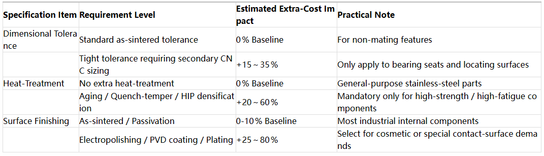
Practical cost‑reduction tactics for specifications
Reserve tight tolerances exclusively for mating assembly surfaces; adopt default as‑sintered tolerance for non‑critical geometry.
Do not add cosmetic surface‑treatment for internal hidden components that will not be exposed to end‑use environment.
Merge identical post‑processing work into one production batch to dilute fixed setup charges.
Harbermetal: Your Trusted precision MIM Parts Partner In China
Many buyers receive high MIM quotations and think raw material prices are the only reason, while ignoring unreasonable tolerances, poor geometry design and unnecessary post‑processing requirements inflate the total budget. You don’t need to spend multiple sampling cycles paying for avoidable manufacturing risks. Send your 2D/3D drawings and functional requirements to Harbermetal. Our engineering team provides pre‑tooling DFM cost‑optimization review, points out over‑specified items and offers material & geometry adjustment suggestions before you invest in MIM moulds.
Harbermetal mim Machining Factory Case Study
Tight sizing tolerances were applied to non‑contact outer profiles, creating large secondary‑CNC workload that delivered zero functional benefit.
Full‑part HIP treatment was specified, while only gear‑tooth contact zones bore cyclic fatigue loads.
Electropolishing requirement covered internal hidden cavities that would never be exposed during service.
Restrict tight CNC‑sizing tolerance purely to gear‑tooth mating surfaces; revert outer non‑functional contours to standard as‑sintered tolerance.
Cancel full‑component HIP treatment; rely on high‑quality sintering process to achieve ≥97 % density, and only keep mandatory H1025 aging heat‑treatment for strength requirement.
Remove electropolishing for internal hidden cavities; retain passivation only for external exposed surfaces.
Contact informationEmail: sales@harber‑mim.comTel: +86 0769‑82389116