en
 de
 jp
 kor
 fra
 spa
 ru
 pt
 it


What Is Knurling? Working Principle, Types & Uses (2026)
Here is a complete guide to knurling: working principle, types, advantages, and applications.
Knurling is a manufacturing process in which a hardened tool with a pattern on it is pressed against a rotating workpiece using a machine. It is commonly done on a lathe. It produces straight, diamond-shaped or diagonal ridges on the metal to reduce slipping. It also supports press fits, enhances grip and adds visual appeal. There are primarily two methods for knurling metal. Form knurling displaces the metal and increases its diameter, whereas cut knurling removes material and reduces the diameter.
Most people have probably used a knurled knob or thumbscrew at some time, but very few people think about how they are made. Most guides will just tell you that knurling “improves grip,” but few will discuss selection problems such as pitch, material, diameter growth, and other factors associated with it. The working principle, advantages, types and applications are covered briefly, along with the trade-offs involved in specifying or machining a knurl correctly.
Key Takeaways
● An operation that adds straight, diamond or diagonal patterns to the surface of a part is called knurling. The process of forming these patterns is also termed knurling.
● The process of removing metal and increasing the size of cylindrical parts can be visualized and explained through two forms of knurling.
● The basic types of knurling are straight, diagonal and diamond, and each is coded with numbers in some institutions.
● Knurling refers to the process of creating a pattern on the surface of objects like knobs, shafts, and sleeves.
● The choice of method depends on the material and wall thickness. Form knurling is best for ductile metals like brass or aluminum. Cut knurling is best for hard, thin-walled parts or for parts that work-harden.
● In knurling, the increase in diameter is about 70% of the pitch. To calculate the diameter before machining, the blank diameter needs to be computed (Aims Industrial, 2026).
● Most lathe user guides and advice give “tested” cutting speeds and feeds, but they vary so much.
What Is Knurling in Machining?
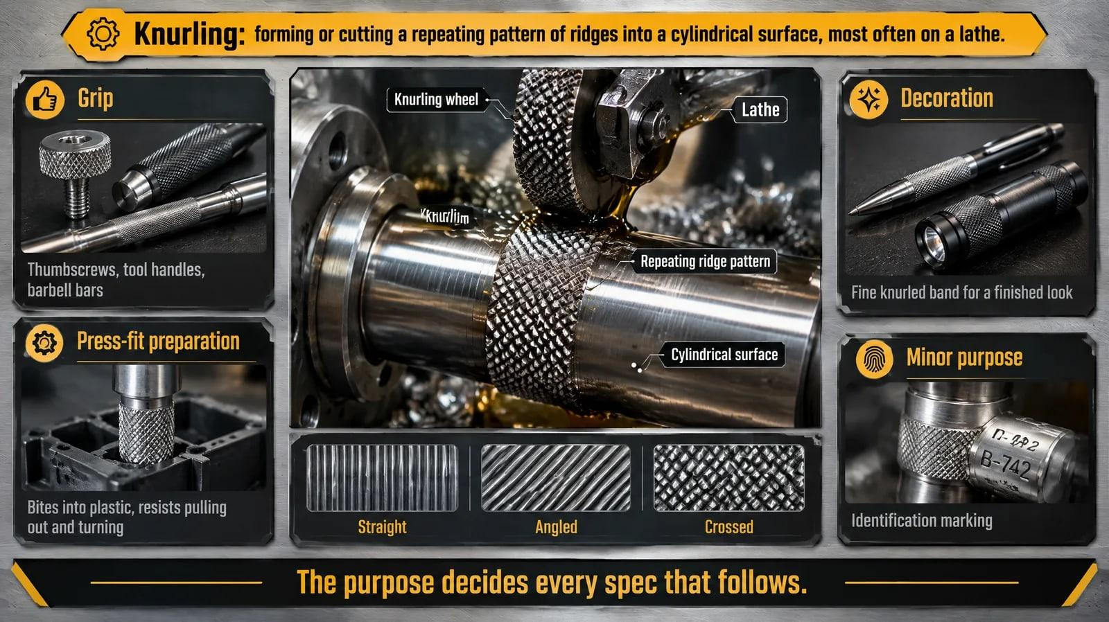
Knurling is a manufacturing process that forms or cuts a repeating pattern of ridges on a cylinder, typically on a lathe. It involves rolling a pattern of straight, angled or crossed lines into the material. It creates a rough band, like those on a thumbscrew or a tool handle.
Three objectives border Xometry knurling (Source: Xometry, 2026):
● Grip: Our thumbscrews, tool handles and barbell bars give us something to hold on to.
● The decoration is a knurled band on a higher-quality pen or flashlight body, which gives it a refined appearance.
● To prepare it for press-fitting, the manufacturers knurl the metal pin. It grips into the plastic and holds firmly.
Additionally, an identification marking serves as a minor purpose.
Just like the other specifications, the decorative band and the press-fit pin are selected based on their purpose. The decorative band has a fine pitch and shallow knurl. The press-fit pin does not require a controlled OD and has no flutes, as the interference in the hole is determined by the peak diameter of the knurl. If we intentionally or mistakenly mix them up, we end up with a bad-looking part that cannot be assembled.
How exactly does the knurling process work?
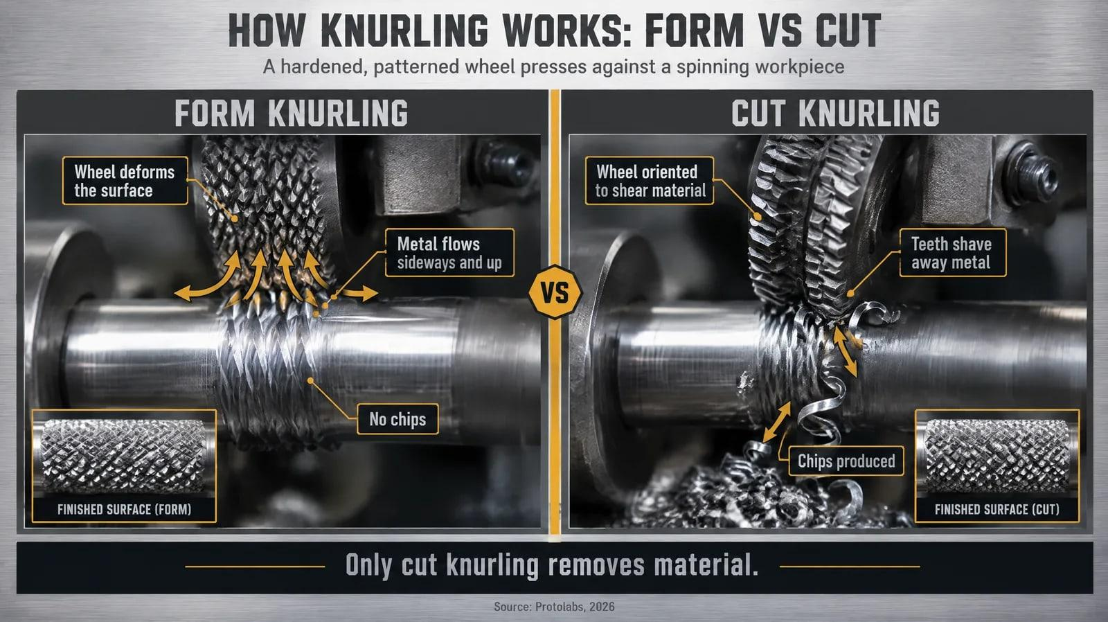
It should be noted that while knurling entails pressing a patterned hard wheel into the object being worked, the teeth of the wheel create a repetitive pattern. Hence, the process described by Protolabs is very similar to knurling. There are two primary knurling methods, which differ based on the force applied and how the metal flows.
In form knurling, the process consists of certain steps: a wheel is pressed down, and the material deforms. This leads to the sideways and upward flow of metal into ridges, and no chips come off. That is, no material is removed. In cut knurling, the wheel is aligned so that its teeth shave off material, forming chips. Ghide and other sources define all knurling as chipping away material, which is accurate only for cut knurling.
What is cut knurling, and what is form knurling?
Faster than cut knurling, it is suitable for ductile metals. Slower than forming knurling, it is suitable for thinner walls, harder materials, and parts with tight diameter tolerances. The following table combines the best guidance from Jiga and ECOREPRAP.
Factor | Form knurling | Cut knurling |
What happens to the metal | Displaced, no chips | Removed as chips |
Diameter change | Increases | None, or a small decrease |
Best materials | Ductile: brass, aluminum | Hard or work-hardening: stainless, titanium; also plastics like Delrin |
Thin or brittle walls | Poor choice | Better choice |
Cycle time | Faster in high volume | Slower |
Typical problems | Burrs, flaking, bent slender parts | Chip tangling, faster tool wear |
We used the following sources for this article: Jiga, 2026; ECOREPRAP, 2025; and Machinist Guides (for plastics).
Is the part diameter increased or decreased by the knurling?
The diameter will increase with form knurling. You can predict how much it will increase: by approximately 70% of the pitch. For example, a 1.0 mm pitch will add 0.7 mm to the overall diameter, or 0.35 mm on each side (Aims Industrial, 2026). MSC Industrial Supply says that the diameter will decrease when you use cut knurling, while another source says that the diameter will not change. There is a small difference between the two methods, so test it first.
We find different kinds of knurling patterns.
Knurling patterns come in three main types: straight, with ridges that run parallel to the axis of the part; diagonal, with a spiral that runs left or right along the part; and diamond, with two sets of diagonal ridges that cross each other.
According to JLCCNC, diamond is recommended for general grip, while “straight” is used when movement is mostly along the axis (Source: JLCCNC, 2026). ECOREPRAP suggested a trade-off: diamond is best for multidirectional plunging but requires rigid tooling, while “straight” plunges in a single direction (Source: ECOREPRAP, 2025).
The meaning of DIN 82 knurling codes.
DIN 82 is a standard for naming knurl patterns using letter codes and pitch. Common patterns are specified below, and the designation should include the pitch. For example, RGE 0.8 indicates a raised diamond pattern with a pitch of 0.8 (Aims Industrial, 2026).
Code | Pattern |
RAA | Straight |
RBL | Diagonal, left-hand |
RBR | Diagonal, right-hand |
RGE | Diamond, raised points |
RGV | Diamond, depressed points |
The inch is another standard in ANSI B94.6 and ISO 13444 (Make-X, “Knurling: Everything You Need to Know,” https://xmake.com/knurling-everything-you-need-to-know/, [2023]).
The meanings of the codes are not agreed upon across different sources. One valve specification source assigns the meaning “diamond” to RKE/RGV. Another source, an acronym guide called Aims Industrial, briefly maps “diamond” to RGE and RGV, and “90° cross pattern” to RKE/RKV.
Knurls are also grouped by location as follows: band, full, internal, face and taper (Fractory, 2026).
How can you select the pattern, shell, method and material?
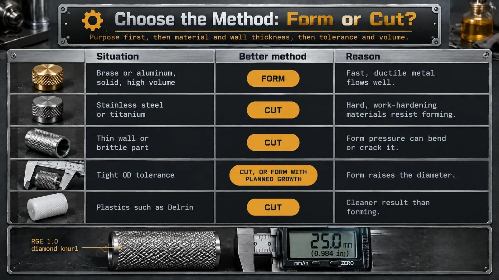
First choose based on purpose, then material and wall thickness, and after that, tolerance and volume. The matrix below turns that order into rules of thumb to follow quickly. So, first choose based on the purpose of making the object.
Situation | Better method | Reason |
Brass or aluminum, solid, high volume | Form | Fast, ductile metal flows well |
Stainless steel or titanium | Cut | Hard, work-hardening materials resist forming |
Thin wall or brittle part | Cut | Form pressure can bend or crack it |
Tight OD tolerance | Cut, or form with planned growth | Form raises the diameter |
Plastics such as Delrin | Cut | Cleaner result than forming |
Example: Drawing to a Knurl (worked example)
The drawing callout needs the pattern code, the pitch, the knurled length, and either the blank or finished OD. If you need a finished OD near 25.0 mm (0.984 in) with an RGE 1.0 diamond knurl, and the form growth is 70% of 1.0 mm, or 0.7 mm (0.028 in), then the initial blank OD is 25.0 − 0.7 = 24.3 mm.
Check the number of teeth now. A setup list from the unit says the number of teeth, N = πD/P, should be close to a whole number so the pattern tracks cleanly. Here is the calculation for a tooth number of 24.3 mm: N = 76.3. A diameter of 24.2 mm (0.953 in) gives N = 76.0, and the finished outside diameter becomes 24.9 mm, which is near perfect. The pitch and diameter must always be chosen together, not independently. But other setups don’t always allow for trade-offs. If 24.9 mm isn’t within tolerance, change the pitch and don’t push the blank.
How should you do knurling on a lathe, step by step?
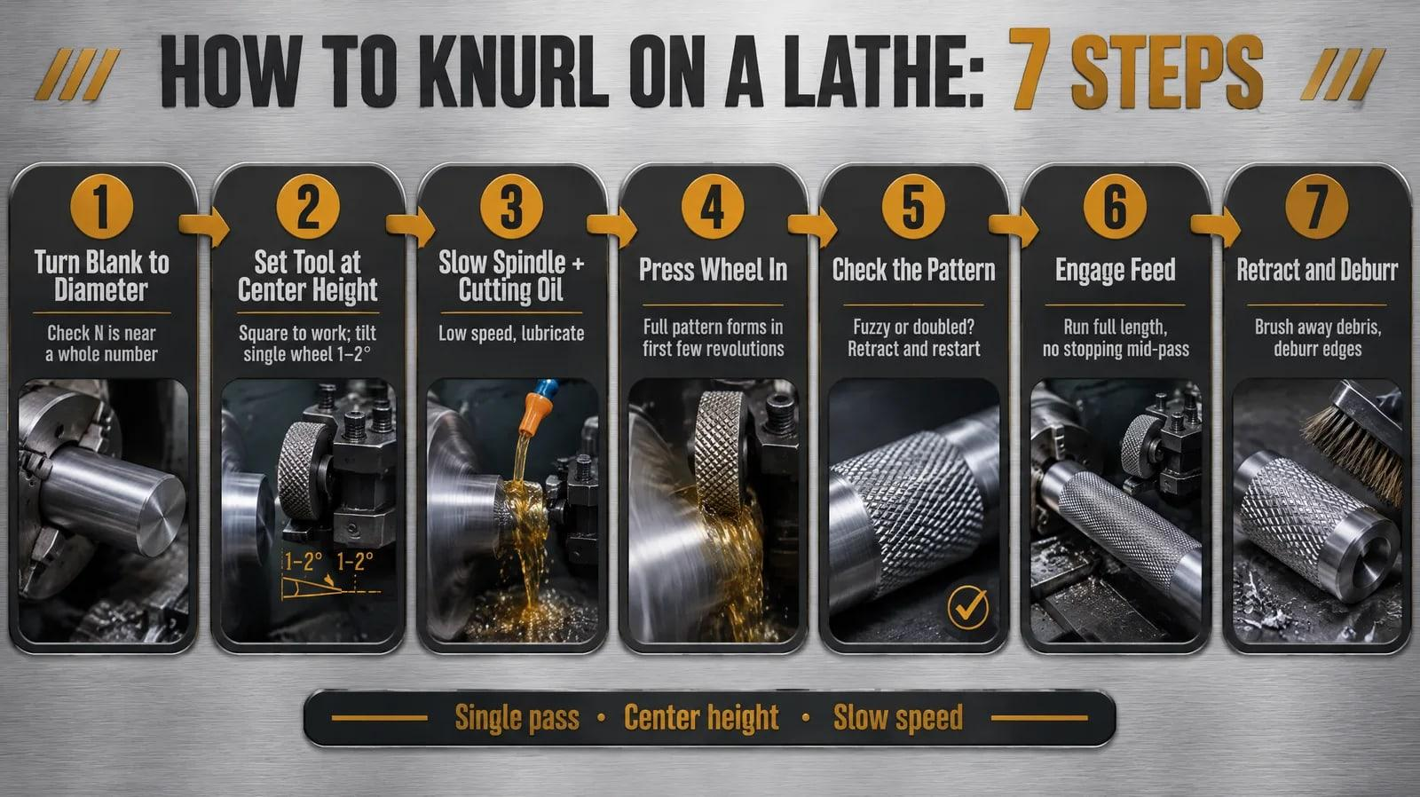
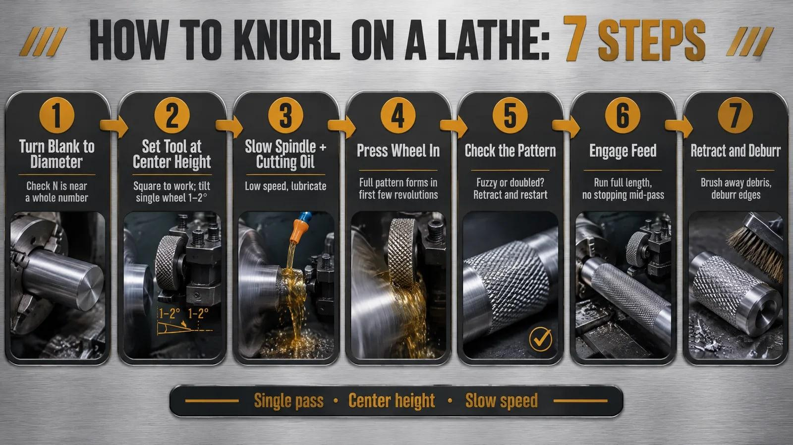
To put knurls on a lathe, set the knurling tool at center height. Lubricate the job. Let the wheel grip tightly and engage it with the spinning blank. Then slowly feed it along the knurl length. All the above setup tips appeared in several guides.
1. Once the diameter has been calculated, turn the reamer against your blank and note the reading “N.”
2. Adjust the knurling tool so it is centred, at the same height as the workpiece, and square to it. Orient a single-wheel tool at 1–2°.
3. Set a slow spindle speed and apply cutting oil.
4. The complete design will form in the first 3–4 revolutions. Thus, a ball is ready.
5. Check the pattern. If it looks fuzzy, blurred or doubled, just back up and start again.
6. Run the whole length of the feed without stopping your pass.
7. Retract, brush away debris and deburr the edges.
What causes the discrepancy in the numbers?
Different published ratings differ due to variations in the machine, material and purpose, so treat the guide’s ranges as starting points.
Parameter | Range | Source |
Spindle speed | 50–200 RPM | |
Power feed | 0.2–0.5 mm/rev | |
Power feed | 0.5–1.0 mm/rev |
The feed range begins at 0.2 mm/rev and ends at 1.0 mm/rev. The upper value is five times the lower one. The two midpoint values are 0.35 and 0.75 mm/rev, respectively, a difference of about 2.1 times. First, scrap the same material, then make any necessary adjustments.
The advantages and limitations of knurling.
Adding knurling to a turned workpiece is a low-budget way to improve its grip, retention, and overall appearance; however, every benefit comes with a design cost.
Advantage | Caveat |
Strong grip | Diamond patterns need rigid tooling |
Better press-fit retention | Diameter growth must be planned |
More durable than rubber, since the pattern is formed into hard material (Source: Xometry, 2026) | Cannot match every ergonomic need |
Low added cost on a lathe | Cut knurling wears tools faster |
Decorative finish | Pitch must suit the part size |
An experiment serves to differentiate fixable shortcomings from more permanent faults. If the issue can be sorted out at the design stage, for example, diameter growth, one is supposed to continue using knurling. If the problem can only be resolved by modifying the process, one ought to rethink.
Knurling is the wrong choice when parts are thin-walled, brittle or less ductile. Users often avoid using knurling to expand a worn piston skirt because machining parts has become cheaper, and performance engine builders don’t recommend it much nowadays.
Knurling is used to create a textured, non-slip surface on parts that need to be gripped or turned by hand, such as tool handles, knobs, and thumbscrews. It can also help press-fit parts together.
Wherever a turned part needs grip, retention, an attractive appearance or a locking surface, knurling is used. Listing the industries that use it is more confusing than helpful.
● The ridge-like structure on the surface of a knob with a cylindrical pattern is known as knurling.
● A threaded bolt that is press-fit into a plastic molding can resist both rotation and pullout.
● Decoration and marking of a fine band over the knobs, styluses, and housings.
● Annular knurling is the lesser-known option that involves ring-shaped grooves instead of ridges.
The same design can be used for various applications with different specifications. The knurl design on a dart barrel is judged by feel; thus, pitch and comfort are matters of preference. A knurl design on a pin is judged by pull-out force; therefore, pitch and diameter are engineering limits.
Common problems with knurling include:
- Uneven or inconsistent patterns caused by poor alignment, incorrect pressure, or a damaged knurling tool.
- Poor pattern definition when the workpiece or tool is moving too quickly, or the tool is not pressed firmly enough.
- Tearing or rough surfaces from excessive pressure, a dull tool, or unsuitable material.
- Workpiece bending or deflection, especially with long or thin parts that lack support.
- Excessive tool wear or breakage due to incorrect speeds, pressure, or lubrication.
- Oversized or undersized diameters because knurling displaces material and changes the part’s dimensions.
- Chatter and vibration, which can leave an irregular finish and damage the tool or workpiece.
- Poor chip and debris control, as displaced material can build up around the tool and affect the pattern.
Knurling problems usually originate from making the same mistake over and over: pushing hard rather than stopping and setting up the machine. The table provides symptoms, along with their causes and solutions, taken from ECOREPRAP, Centre Lathe and various other sources.
Symptom | Likely cause | Fix |
Fuzzy or double-cut pattern | Wrong blank diameter or poor tracking | Retract, re-check the diameter and restart |
Shallow knurl | Too little pressure or wrong diameter | Re-engage fully on one firm pass |
Wear rings | Stopping mid-pass | Run the full length in one pass |
Flaking or burrs | Form method on a hard material | Switch to cut knurling |
Bent slender part | Too much radial force | Support the part or use cut knurling |
Chip tangling | Cut knurling debris | Clear chips often, use lubricant |
Ruined diameter | Over-knurling | Stop once the pattern is full |
Frequently Asked Questions
<h3 style="margin-top:1