
Metal Injection Molding Tolerances
Metal injection molding is a versatile manufacturing method ideal for mass complex metal parts production. Metal Injection Molding (MIM) is a method of creating granulated raw materials by combining fine metal powders (aluminum, magnesium, steel, etc.) with binder agents (various thermoplastics, waxes, and other materials). The granulated feedstock is then used in a conventional injection molding machine.MIM is limited to relatively small parts, usually made of highly complex geometries.. This allows manufacturers to quickly and economically produce high volumes of identical components that reliably meet strict mechanical requirements.

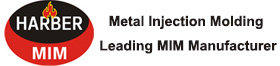
Metal Injection Molding mim parts tolerances are nominally ±0.3%-0.5%, although tighter tolerances can be achieved in some cases if deemed essential. MIM component production ranges over a large size range, making it difficult to address tolerances directly over such a wide range. In some instances, the choice has been to create a table of tolerance versus size, showing capabilities as follows: These MIM tolerances can be obtained within a single batch but wider variation is usually observed over time.
± 0.03 mm (0.0012 inch) for features below 3 mm (0.12 inch)
± 0.05 mm (0.002 inch) for features between 3 and 6 mm (0.12 to 0.25 inch)
± 0.08 mm (0.003 inch) for features between 6 and 15 mm (0.25 to 0.6 inch)
± 0.15 mm (0.006 inch) for features between 15 and 30 mm (0.6 to 1.2 inch)
± 0.25 mm (0.01 inch) for features between 30 and 60 mm (1.2 to 2.4 inch).
The microstructure of the mim parts is uniform, with high density and good performance
MIM is a fluid forming process, and the presence of adhesives ensures the uniform distribution of the powder, thereby eliminating the microstructure non-uniformity of the blank, and allowing the sintered product density to reach its theoretical density.
Generally speaking, MIM can achieve a density of 95% to 99% of the theoretical density. The high density can increase the strength, enhance toughness, improve ductility, and enhance electrical and thermal conductivity of MIM parts. It also improves magnetic properties.
On the other hand, traditional powder forming and pressing of parts can only achieve a maximum density of 85% of the theoretical density. This is mainly due to the frictional forces between the mold wall and the powder, as well as between powder particles, causing uneven distribution of pressing pressure. This uneven pressure distribution leads to non-uniform microstructure of the pressed compact, resulting in uneven shrinkage during the sintering process. As a result, the sintered powder metallurgy part has larger porosity, lower density, and poor compactness, which seriously affects the mechanical properties of the part.
Issues to Consider in MIM Injection Molding Dimensions
When designing MIM parts, the determination of tolerances for MIM products should be considered from two aspects:
1. What level of tolerance can be achieved with MIM technology.
2. What level of tolerance is required for the product.
MIM Parts Dimensional Tolerance
The tolerances of MIM parts are influenced by many factors, such as mold design, dimensions, shape, material, gate position, number of cavities, mold structure, annual production batch, and repair techniques.
Generally, the ability to control tolerances will gradually improve with accumulated experience in the production process. Initially, the linear dimensional tolerance of MIM products can only be controlled within about 0.5%, but by strict control of MIM process parameters, the linear dimensional tolerance can be controlled within about 0.3%. As the part size decreases, narrower dimensional tolerances can be achieved. However, the reduction in tolerance is not directly proportional to the reduction in size and also depends on the raw materials, part shape, and process requirements. For some small-sized products, if the mold works well, a dimensional tolerance of about 0.1% can be expected. With the development of new binder systems and overall process control, the above tolerance values are expected to improve.
MIM is isotropic, and the dimensional changes in all directions are almost consistent, while the influence of anisotropy is minor and weak. However, when the formed part is subjected to weak external forces, such as the viscous force of the mold during injection molding, gravity during binder removal, and friction resistance of the baseplate during sintering shrinkage, dimensional changes will occur. Therefore, these small deformations must be considered in mold design.
Optimizing Metal Injection Molding Tolerances
Injection molds are typically CNC machined to tolerances of +/- 0.005 inches, unless more restrictive tolerances are required. In general, “tight tolerance” metal injection molding refers to +/-.002 inches in variation, and “very tight” to +/-.001 inches. Normal tolerances for metal injection molding tend to be less expensive to manufacture than parts with tight tolerances, which is why determining the optimal tolerance for a particular part is vital for producing high quality parts at an affordable rate.
Here are some metal injection molding tolerance guidelines that designers and engineers can follow to optimize metal part tolerances:
1. Design metal parts for manufacturability
Anticipating tolerance concerns early in the design phase is key to preventing costly and time-consuming redesigns during later stages of production. To minimize the potential for warping and part misalignments, designers should ensure that they are adhering to design for manufacturability (DFM) best practices. DFM principles entail designing metal parts with the specific method of manufacturing in mind. The manufacturing method — and its unique restrictions — should inform factors such as wall thickness, draft angles, and design features like bosses.
2. Select the ideal metal material for the application
The tolerance of injection-molded metal parts can also be significantly impacted by metal material — which is why material selection is equally as important as part design. Shrinkage tolerances in MIM are important to consider as the metal undergoes changes in size during the debinding and sintering stages. The specific shrinkage tolerances for MIM can vary depending on factors such as the metal alloy being used, the geometry of the part, and the desired final dimensions.
Generally, the shrinkage tolerances for MIM are typically in the range of +/- 0.5% to +/- 2% of the nominal dimensions. This means that the final dimensions of the part may be slightly smaller or larger than the intended design dimensions due to the shrinkage that occurs during the debinding and sintering processes.
3. Keep tooling considerations in mind
Because mold tools are typically designed to be slightly oversized — to account for material shrinkage — it’s important to first determine which material(s) will be used. Well-designed tools play an integral role in ensuring that injection molding metal parts cool properly and adhere to strict injection molding tolerance standards.
It is important for MIM manufacturers to account for these shrinkage tolerances when designing the mold and specifying the dimensions of the part. This can be done by adjusting the initial part geometry and dimensions to account for the expected shrinkage, as well as by conducting post-processing operations such as machining or grinding to achieve the desired final dimensions.
4. Implement repeatable process controls
Manufacturing processes involve a significant number of variables that can affect the viability and quality of a part, and process controls are a means of calibrating these variables so as to minimize deviation.
It is recommended to consult with MIM manufacturers or industry standards to determine the specific shrinkage tolerances for the metal alloy and part geometry being used in order to ensure accurate and precise production of MIM parts.
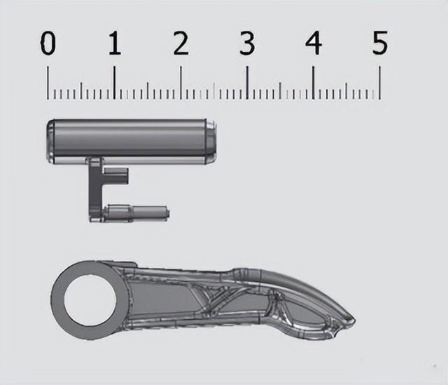
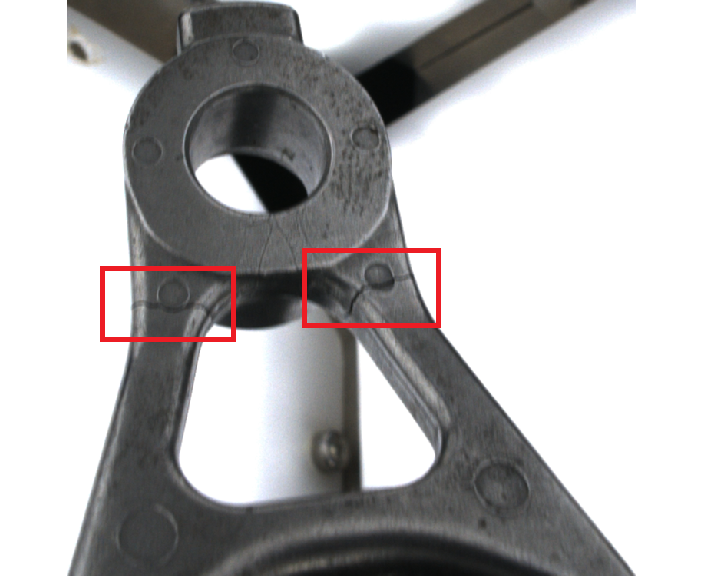
Common Defects of MIM Workpiece
MIM combines the two major processes of powder metallurgy and plastic injection, and the common defects of workpieces include cracks, sticky materials, sticky plates, missing materials, pits, abrasions, pockmarks, etc.
a)Cracks
b)Sticky material
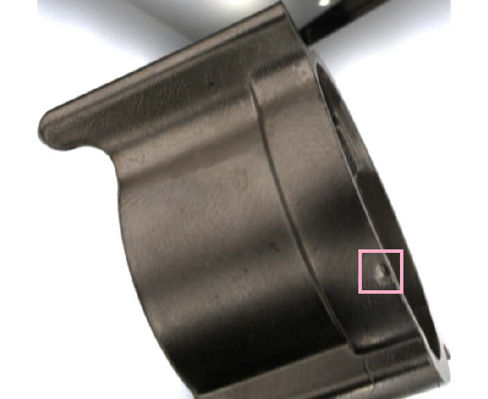
c)Pits
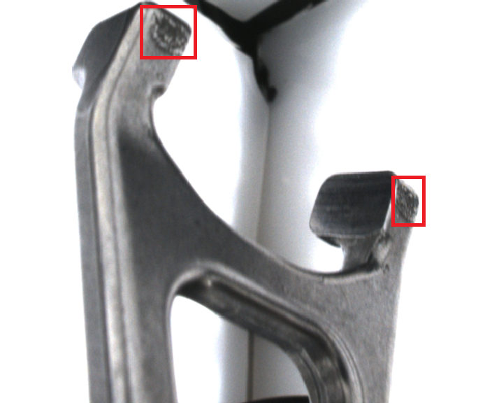
b)Sticky plate
Figure 3 Examples of common defects on a MIM part.
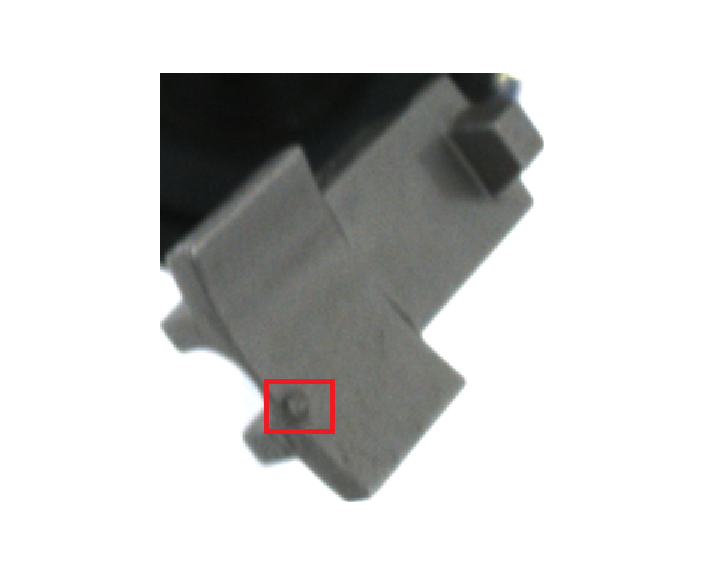
Harber Metal Using high-speed inspection platform and target inspection model, the defect detection needs of MIM workpieces are well solved. On the workpieces provided by a MIM manufacturer in Wujiang, the results were excellent, with the accuracy rate of abnormal parts exceeding 95.37%, meeting customer requirements.
The accuracy rate of normal parts exceeds 99.99%, meeting the requirements.
The accuracy rate of abnormal parts exceeds 95.37%, meeting the requirements.
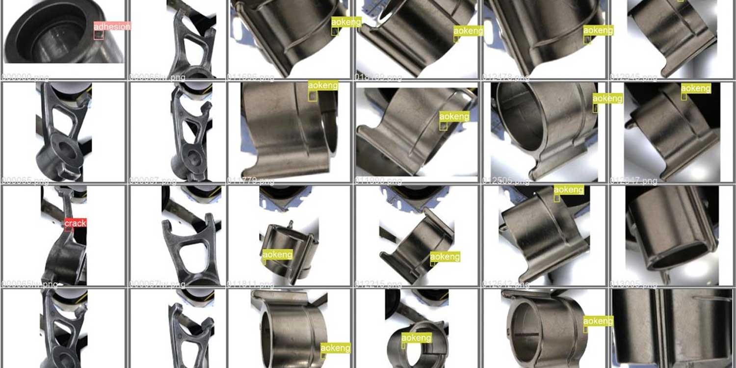
Figure 4 Example of MIM Defect AI Prediction Translated into English